- The Sugiyama layout algorithm is actually a set of algorithms all folded into one. The various algorithms that make up the sugiyama algorithm have been reviewed and updated over the years.
- Set theory is everything to understanding the Sugiyama algorithm. It seems that a lot of authors (Sugiyama included...) use set theory symbols to denote the various algorithms within Sugiyama. Now i haven't used set theory in two years and you can imagine the strain i had having to refresh myself when it came to set theory notation. It wasn't all that bad...just slowed me down a bit
- Lots of guys struggle with understanding the Sugiyama layout algorithm and so i hope that this blog post makes it easy for folks to take that first step in quickly understanding the Sugiyama Layout algorithm.
In this blog post, i am going to try and demystify the hierachial layout algorithm commonly known as Sugiyama to make it easy for anyone using advanced texts to better understand what the Sugiyama algorithm is all about.
What is the Sugiyama Layout algorithm?
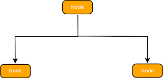
The Sugiyama layout algorithm is actually a set of algorithms that were defined by Sugiyama et al in the late 80's. The idea behind these set of algorithms that make up the Sugiyama layout algorithm was to enable the automatic layout of nodes(sometimes called vertices) and edges to a hierachial fashion. If one thinks of a chart of UML diagrams with inherited classes, then the nodes(or vertices) would be the class diagrams (for instance) with the various propoerties and methods and the edges would be the lines connecting the various vertices/Nodes. To make this blog posting more palatable, i will avoid using set theory as much as possible. easy peasy...
While it would be easy for humans to create a hierachial diagram that is visually appealing, it's another thing all together to have this automatically done with a piece of computer software but this is what exactly the sugiyama algorithm aids to do
<Fig 1: Example of Hierarchical diagram - graph, layer, vertice/Node, edge>
To understand the Sugiyama layout algorithm, one has to first undertand what a visually appealing hierachial diagram is...then the code to automatically lay out the nodes because possible to write. The Sugiyama algorithm lays out a number of conditions that define what a visually appealing hierahial diagram should fulfil:
- The number of upward facing edges should be minimised (hierachy)
- Vertices should be placed in layers and as uniformly as possible in these layers (uniform distribution)
- The number of layers that the edges span should be minimised as much as possible (edges length minimization)
- Edges crossings should be minimized as much as possible (edge crossings minimization)
- Isomorphic graphs should be drawn identically (identical drawing)
- On each layer, vertices should be separated by the smallest distance possible (smallest separation)
- Neighbouring vertices in neighbouring layers should be placed as close as possible (closeness)
- Each vertice should be placed at the barycenter of the neighbouring vertices (balance)
- Bends should be minimised and edges made as straight as possible (linearity)
Don't worry if the above rules don't make sense right now. As you go through the blog post, it will become apparent what the terms 'barycenter' or 'isomorphic graph' mean.
Great, but what exactly is the Sugiyama algorithm and how does it work?
You will notice that above, i just mention what the Sugiyama algorithm is meant to do i.e. automatically lay out nodes in a hierarchial fashion...but it does not explicitly explain how that happens! Well, that';s what this section is all about...explaining how the Sugiyama algorithm works before i delve into the finer details using source code to provide a more detailed explanation.
The Sugiyama algorithm lays out the vertices in a graph (which coincidentally must be an acyclic digraph i.e. a directed graph (the edges have arrows or direction) and where no set of the edges form a cycle) in four stages
- The graph is made acyclic (i.e. any cycles formed by edges in the graph are removed). Details of how this is done below
- Vertices are assigned to layers in the graph
- The order of vertices in each layer is determined to reduce edge crossings as much as possible
- The position of the reordered vertices in each layer is determined to enhance balance and closeness.
Four mysterious stages(or algorithms)....that makes up Sugiyama!
There are obviously a lot more details that one will need to understand about each of the four steps above to clearly visualize the internals of Sugiyama. I will go through the four steps above using source code in java to clearly explain the four steps of Sugiyama and how they work.
Before we go on...
You are free to code the nodes/vertices and edges in your software as you see fit. I will explain the way i did it (a model i will be using all through the blog post) but feel free to adapt it to your source code once the stages below are clear.
The Graph that contains all the nodes and edges is denoted by the instance:
Graph graph = graphFrame.getGraph();
Edges are denoted and obtained from an arraylist of all the edges by the following code:
Edge e = (Edge)graphEdges.get(i); // i defines the index/counter for the current edge retrieved
Vertices are denoted and obtained by the following code:
Node n = (Node) graphNodes.get(t) // t is the counter for the current node retrieved
Step 1: making the graph Acyclic
I'll be a bad guy and let you figure this one out. Here's the reason why. When i was implementing the Sugiyama code, i knew the context that the software would be used...to lay out UML diagrams and if you think about it for a second, you will see that it becomes very difficult to create cycles..but i do promose to get back with code on how to do this later.
Step 2: Assigning vertices to layers
This step actually involves 2 steps; assigning vertices to layers in the graph and inserting dummy vertices. Dummy vertices...what's that? Well here's the thing. An edge in a graph(according to the Sugiyama algorithm should have a span of on 1) i.e. it should interconnect 2 vertices in adjacent layers. However, a vertice may be in layer 2 while connected to a vertice in layer 4; thus the edge would have a span of 2. Thus this step involves not just assigning the vertice to a layer but inserting dummy vertices to edges that have a span of 1. So the question remains...what criteria is used to assign vertices/nodes to layers. Simple
First select the root nodes. These are the nodes that have edges flowing away from them but none coming into them. Then from each of the root nodes recursively go through all the nodes in the graph incrementing the level that a graph should have and assigning this level to the graph. If a node/vertice with a level assigned is encountered, check if the proposed level that it is to be assigned is less than the current level. If this is the case, assign it the proposed level (that is greater than the initial node level)

Here's a method referred to as getNodeChildren() with the signature indicated:
I'll be a bad guy and let you figure this one out. Here's the reason why. When i was implementing the Sugiyama code, i knew the context that the software would be used...to lay out UML diagrams and if you think about it for a second, you will see that it becomes very difficult to create cycles..but i do promose to get back with code on how to do this later.
Step 2: Assigning vertices to layers
This step actually involves 2 steps; assigning vertices to layers in the graph and inserting dummy vertices. Dummy vertices...what's that? Well here's the thing. An edge in a graph(according to the Sugiyama algorithm should have a span of on 1) i.e. it should interconnect 2 vertices in adjacent layers. However, a vertice may be in layer 2 while connected to a vertice in layer 4; thus the edge would have a span of 2. Thus this step involves not just assigning the vertice to a layer but inserting dummy vertices to edges that have a span of 1. So the question remains...what criteria is used to assign vertices/nodes to layers. Simple
First select the root nodes. These are the nodes that have edges flowing away from them but none coming into them. Then from each of the root nodes recursively go through all the nodes in the graph incrementing the level that a graph should have and assigning this level to the graph. If a node/vertice with a level assigned is encountered, check if the proposed level that it is to be assigned is less than the current level. If this is the case, assign it the proposed level (that is greater than the initial node level)

<fig 2: flow diagram of the algorithm to assigning levels to the nodes in a graph>
Here's a method referred to as getNodeChildren() with the signature indicated:
 private Node getNodeChildren(Node n, ArrayList graphEdges, Integer startCounter)
    {
        /**
         * The algorithmn for this function is as given below
         * starting with sourceNode 0,
         *      loop through all the edges
         *      find which edges have source Node as sourceNode0
         *      get the endNodes for these edges
         *      Add these endNodes as the childNodes for recursion
         *      increment the level that the nodes are found at
         */
        ArrayList endNodes = new ArrayList();
        if(n.getLayer()==-1||startCounter > n.getLayer())
        {
           n.setLayer(startCounter);
        }

        for(int i = 0 ; i 0)
        {
            startCounter += 1;
            for(int k = 0 ; k< endNodes.size(); k++)
            {
                getNodeChildren((Node) endNodes.get(k),graphEdges, startCounter);
            }
        }

        // output the layer at which every node is found
       System.out.println("\nLayer: "
                    + n.getLayer()
                    + " Node: "
                    + n.toString());
        return n;
    }
Once all the nodes have a level(or layer number assigned to them, then comes the next step; adding dummy vertices where the edges have a span of more than 1. To do this, here is a simple function that gets the maximum span of all the edges:
     /**
     * Function gets the maximum span for all edges to allow
     * for the introduction of dummy vertices
     * @param edges
     * @return the max edge span
     */
    public int getMaxSpan(ArrayList edges)
    {
        int maxSpan = 0;

        for(int i=0;imaxSpan)?(endNodeLayer-startNodeLayer)
                    :maxSpan;
        }

        return maxSpan;
    }
Once the spans for all the edges have been determined, now comes the interesting part, the dummy vertices (and edges) are added:
     /**
     * function inserts dummy vertices and breaks down the
     * edges into segments in cases where the edges
     * span is >1
     * @param g the edge whose span is checked if>1
     */
    public void insertDummyVerticesAndEdges(Edge g)
    {
        /**
         * a. Loops through an edge
         *      i. finds out if the span is >1 by checking the
         *          start and End Node layers
         *      ii. Adds dummy vertices if span>1 at
         *          all calculated intermediate points
         *          (endNode.coords - startNode.coords)/span
         *      iii.Add segements to replace edge with start
         *          and end nodes indicated
         * e. remove the long edge whose span >1
         */
        Node startNode = g.getStart();
        Node endNode = g.getEnd();

        // get the span of the edge
        int span = endNode.getLayer()-startNode.getLayer();
        if(span>1)
        {
            System.out.println("\t* Edge "
                    + g.toString()
                    + " has span of "
                    + Integer.toString(span)
                    + " from "
                    + Integer.toString(startNode.getLayer())
                    + " to "
                    + Integer.toString(endNode.getLayer()));

            // calculate the incremental positions for the
            // display of the dummy vertices
            double xIncrement = (endNode.getBounds().getCenterX()
                                        - startNode.getBounds().getCenterX())/span;
            double yIncrement = (endNode.getBounds().getCenterY()
                                        - startNode.getBounds().getCenterY())/span ;

            // add dummy vertice at the various
            // layers that the edge spans
            // dummy_vertices_added  = (span -1)
            // @todo create a dummyNode vertice
            int noDummyVertices = span -1;
            Node previousNode = startNode;

            for(int i = 0 , currLayer = startNode.getLayer() + 1
                    ; i < noDummyVertices
                    ; i++ , currLayer++)
            {
                PointNode d = new PointNode();
                d.setLayer(currLayer);

                // show that it's a dummy variable
                d.setDummy();

                // add the Node to the graphs set of Nodes
                // get the dummy vertices coordinates
                final double xCoord = previousNode.getBounds().getCenterX()
                                    + xIncrement;
                final double yCoord = previousNode.getBounds().getCenterY()
                                    + yIncrement;

                // add Dummy Node
                graph.add(d, new Point2D.Double(xCoord,yCoord));

                System.out.println("\t\tAdded Dummy Node "
                        + d.toString()
                        + " at Layer "
                        + Integer.toString(d.getLayer())
                        + " and coords "
                        + d.getBounds()
                        + " ["
                        + Double.toString(xCoord)
                        + ","
                        + Double.toString(yCoord)
                        +"]");

                // add edge joining previous node
                // to newly created node
                // create new edge
                ClassRelationshipEdge r = new ClassRelationshipEdge();

                // connect the Nodes using the new edge
                graph.connect(r, previousNode, d);

                System.out.println("\t\t\tAdded new edge "
                        + r.toString()
                        + " at "
                        + previousNode.getBounds()
                        + " to "
                        + d.getBounds());

                // make sure that the final edge between
                // the last dummy variable and endNode
                // is plotted
                if(i==noDummyVertices-1)
                {
                    // create new edge
                    ClassRelationshipEdge lastEdge = new ClassRelationshipEdge();

                    // connect the Nodes using the new edge
                    graph.connect(lastEdge, d, endNode);

                    System.out.println("\t\t\tAdded Last edge "
                        + r.toString()
                        + " at "
                        + d.getBounds()
                        + " to "
                        + endNode.getBounds());
                }

                // set the previous Node to the current
                // highlighted Node
                previousNode = d;
            }

            // since edge is decomposed to various
            // segments linking the various
            // dummy vertices, remove the edge
            graph.removeEdge(g);
        }
        else
        {
            // span is 1, OK
            // do nothing...
             return;
        }
    }
Step 3: Ordering the vertices to reduce the number of edge crossings:
So now all the nodes have been assigned to specific layers and dummy nodes (and by extension dummy edges) have been added. However, the vertices in each of the layers may be ordered in such a way that a lot of the edges connecting vertices(including the dummy vertices) between adjacent levels are crossing each other a lot. This is highly unacceptable and from the list of aethestic considerations below, the reduction of edge crossings is a key feature of the algorithm

<fig 3: a graph with a lot of edge crossings and one with few edge crossings>
So how do we reorder the vertices in each of the levels to ensure that the edge crossings are reduced as much as possible?
The number of edge crossings in vertices in adjacent layers is obtained by obtaining the adjacency matrices of the edges in adjacent layers, calculating the barycenters of these adjacency matrices and reordering the nodes so that the barycenters of the nodes are arranged from the smallest to the largest. Once a reordering occurs, the barycenters are recalculated and reordering done until the minimum number of edge crossings are obtained.
<fig 3: flow diagram illustrating the algorithm>
I realise that the description above is as cryptic as, well...trying to figure out how to make a chicken sing and so i'll try break down the various components of this step:
(a) Obtaining the adjacency matrices of adjacent layers in the graph where the vertices have been assigned layers
PS: I have had this article in my archives for very long before i decide to publish it. Please let me know if there are any errors &/ ommisions in the comment section below