Saturday, July 6, 2019

The fastest way for developers to integrate the {daraja} MPESA APIs using Bees (www.bees.software)

Over the course of a year, during the development of Nectar (https://www.nectar.software), one of the most frustrating components was the integration of MPESA as a payment option. And it wasn't because of the technical aspects; the MPESA APIs have a fairly well documented developer portal with details on its REST API endpoints. Rather, it was the arduous manual set up procedure that required a developer to engage with the MPESA Business support team for manual configuration as well as the verbose and unnecessary aspects of the API itself.

In case, you are wondering what Nectar is, Nectar is the most performant STS (IEC 62055-41) compliant prepaid water, electricity and gas cloud based SaaS available. It allows service providers offering water, electricity and gas services to get payment for these services from their customers *before* usage at zero cost. This way, the service providers do not have to read meters or disconnect services while customers pay for exactly what they need and cannot afford. More details are available at https://www.nectar.software. Clearly, in Kenya, allowing payment for services using MPESA using the MPESA APIs was absolutely necessary.

In total, it took me 3 months of back-and-forth with the MPESA Business team to get MPESA integration working. During this time, I had to incorporate a company, open a bank account with a major bank and modify the MPESA short code from a Till No to a Paybill No, the latter being that a reference (really a short additional note) can be added per transaction. Various APIs also required mundane information for example the Lipa Na MPESA API that requires a 'Timestamp' to record when the transaction was initiated. For most instances, I imagine an code/auto-generated 'Timestamp' would be sufficient.

While I understand MPESA's need to prevent money laundering via their API, it seemed that for a casual developer hoping to integrate the {daraja} MPESA APIs for a minimal number of payments, the task has been made particularly and unnecessarily complex.

And hence, Bees© was created. Bees© is a platform that provides REST endpoints allowing developers to integrate MPESA APIs into their applications in mere minutes.  Bees© has already obtained Safaricom MPESA G2 API integration. Using this integration, Bees© provides a succinct, intuitive and easy to use wrapper API to allow developers to use the Safaricom MPESA G2 APIs in minutes. Using this Bees© wrapper API, developers create the required Bees© credentials and withdrawal accounts before making REST API calls to trigger STK pushes on their target customers' MPESA-enabled devices or query C2B transaction statuses.

Using Bees© (https://www.bees.software) is simple and requires the following steps that can be done using CuRL requests or the Bees© SDKs.

Create a Bees© account

To create a Bees© account, a developer can either use the registration form available at https://www.bees.software or make a REST request to the Bees© MPESA API. This Bees© REST returns a user_ref to be used in calls to create credential pairs.

curl --request POST \
    --url https://bees.software/v1/user \
    --header 'content-type: application/json' \
    --data '{
             "first_name":"John",
             "last_name":"Doe",
             "username":"username",
             "password":"password",
             "phone_no":"0700100100",
             "email":"info@email.com",
             "image_url":"https://s3.aws.com/avatar.jpeg"
         }'

Or using Bees© Python SDK

bees.get_user_factory().create_user(first_name='John',
                                    last_name='Doe',
                                    username='username',
                                    password='password',
                                    phone_no='0700100100',
                                    email='info@email.com',
                                    image_url='https://s3.aws.com/avatar.jpeg')

Create a Bees© credentials key pair

A credentials key pair is used to authenticate REST API calls and must be kept confidential. To create or delete Bees© credentials (key & secret pairs), a developer must use the profile page in this management portal. Each set of credentials consists of a consumer key and consumer secret with selected permissions.

Create a Bees© withdrawal account

A withdrawal account is an MPESA enabled mobile number or bank account with a Safaricom Paybill No that receives a transaction payment initiated using a Bees© REST API call. To create a Bees© withdrawal account, a developer can either use the profile page or make a REST request to the Bees© MPESA API. The list of supported banks and bank_refs can be obtained using the Bees© MPESA APIs. All transactions (STK Push & C2B) will have their value minus a 3% transaction charge remitted to the specified withdrawal account within 24 hours. No other charges are paid to use the Bees© MPESA APIs.

curl --request POST \
    --url https://bees.software/v1/account/ \
    --header 'authorization: BEES deccf75f6e941e95df6...VhODM1YjRlNDYyMGY1NzY3YjllYWU5OA==' \
    --header 'content-md5: 3A416975F48B8C5E1C2157484091441B' \
    --header 'content-type: application/json' \
    --header 'date: Thu, 17 Nov 2019 18:48:58 GMT' \
    --header 'nonce: 5efdf6947f14325d490bd1d67a93940d' \
    --data '{
             "bank_ref":"3ec0192b733cd6d65bd9f5543dd41e5f",
             "account_no":"123456789"
       }'
             

Or using Bees© Python SDK

bees.get_account_factory().create_account(bank_ref='3ec0192b733cd6d65bd9f5543dd41e5f',
                                          account_no='123456789')
                            

Initiate Bees© REST API payment call

To initiate an STK payment push to a mobile device, use a Bees© credentials (key & secret pair) pair and withdrawals account to prompt payment. The customer whose phone number is included in this request will observe the MPESA STK Push applet initiated on their mobile device with the payment details configured in the API call. Once completed, the transaction status and result of this STK push will be submitted by Bees© to the callback_url specified in this request. The account_ref in this API call must be associated to a valid withdrawal account.

curl --request POST \
    --url https://bees.software/v1/promptSTKPushPayment \
    --header 'authorization: BEES deccf75f6e941e95df6073497214c266:OTZkZm...2YxNDNmZTRiZDAwMQ==' \
    --header 'content-md5: F3216235710FA290C6508C0BFA8B4041' \
    --header 'content-type: application/json' \
    --header 'date: Thu, 17 Nov 2019 18:48:58 GMT' \
    --header 'nonce: 2659c837e161e039ecf23fe47e6db42f' \
    --data '{
             "payment_type":"mpesa_stk_push",
             "payer":"254703133896",
             "callback_url":"https://nectar.software/log.php",
             "displayed_desc":"Sweater",
             "full_desc":"Payment for Sweater",
             "amount":"100",
             "account_ref":"5774a10f60414b67f12abb105235479e",
             "env":"live"
        }'
           

Or using Bees© Python SDK

bees.get_stkpushtransactions_factory().prompt_stkpush_transaction(payment_type=PaymentType.mpesa_stk_push,
                                                                  payer='254703133896',
                                                                  callback_url='https://nectar.software/log.php',
                                                                  displayed_desc='Sweater',
                                                                  full_desc='Payment for Sweater',
                                                                  amount=100,
                                                                  account_ref='5774a10f60414b67f12abb105235479e',
                                                                  env=Env.live)

Alternatively, the Bees© API can be used to poll payments made directly to the short code 826588 for C2B transactions. This creates asynchronous call whose results will be sent to the callback_url specified once the status of the C2B transaction is obtained.

curl --request POST \
  --url https://bees.software/v1/transactions/poll \
  --header 'authorization: BEES deccf75f6e941e95df6073497214c266:NzExOWFlYzEwOW...jY4YWZhNTcwMDg1NjRkZmE3MTlkMA==' \
  --header 'content-md5: D41D8CD98F00B204E9800998ECF8427E' \
  --header 'content-type: application/json' \
  --header 'date: Thu, 17 Nov 2005 18:48:58 GMT'
  --header 'nonce: 815c7150b00b64a934a8162b711650de' \
  --data '{
           "payment_status_type":"mpesa_poll",
           "transaction_id":"NEN14BDQZH",
           "callback_url":"https://nectar.software/log.php",
           "env":"live"
  }'

Or using Bees© Python SDK

bees.get_c2btransactions_factory().poll_transaction(payment_status_type=PaymentStatusType.mpesa_poll,
                                                    transaction_id='NEN14BDQZH',
                                                    callback_url='https://nectar.software/log.php',
                                                    env=Env.live)

Details on Bees© can be obtained at www.bees.software and the SDKs found at https://bitbucket.org/account/user/nectar_co_ke/projects/BS

Bees© dashboards

Bees© has a number of dashboards that allow developers to keep track of the number of STKPush and C2B transactions initiated or referenced to their credentials. Dashboard charts and elements include
  1. Generated transaction revenue
  2. Number of transactions
  3. Devices used when using the Bees© APIs
  4. SDK/REST API usage
  5. Location from which requests are initiated
Log in to the Bees© dashboard to experience a better way to manage your {daraja} M-PESA API transactions.


feature

Tuesday, July 24, 2018

An nginx php-fpm configuration for moodle 3.5


I had issues running Moodle 3.5.1 on my Ubuntu 16.04 VM running on Virtualbox.

The configuration below in the nginx configuration (/etc/nginx/sites-enabled/default) to make sure the links to the required resources redirect to the correct locations


Tuesday, July 19, 2016

Setting up Celery, python3, Celery flower and rabbitmq on mac 10.9.5

The following are the steps required to install celery, flower and rabbitmq on a mac 10.9.5 


Install python3

> brew install python3
> python3 -V # should display the version

Install and run rabbitmq

> brew install rabbitmq
> sudo rabbitmq-server # should run the rabbitmq server

# if the rabbitmq-server returns an error like “not_a_dets_file”, then delete the dets file. This is usually due to incorrect shutdown of the rabbitmq-server

> rm /usr/local/var/lib/rabbitmq/mnesia/rabbit\@localhost/recovery.dets

RabbitMQ can now be accessed on localhost:15672

Install celery 

> brew install celery
> mkdir & cd celery_tasks
> vim tasks.py

from celery import Celery

# first arg is the name to be prepended to the tasks
# backend param is an optional tag to retrieve the status of a backrgound running task
# broker is the broker service that routes the incoming and the outgoing messages
app = Celery('tasks', backend='amqp', broker='amqp://')

# all tasks must be decorated
@app.task(ignore_result=True)
def print_hello():
    print ('hello there')


# a task to generate prime numbers that should take time
@app.task
def gen_prime(x):
    multiples=[]
    results=[]
    for i in range(2,x+1):
        if i not in multiples:
            results.append(i)
            for j in range(i*i,x+1,i):
                multiples.append(j)
    return results

> celery worker -A tasks &

- To run the actual tasks
> python3
> from tasks import print_hello
> from tasks import gen_prime
> print_hello()
> primes=gen_prime(1000)
> print primes
> # to check if the task is complete
> primes.ready()
> # to get the results
> print primes.get()

Install Celery flower 

> pip3 install flower
> flower —port 5555
> # accessing flower on the port should show the list of active tasks

Celery flower can now be accessed on localhost:5555

Interesting links 

https://www.digitalocean.com/community/tutorials/how-to-use-celery-with-rabbitmq-to-queue-tasks-on-an-ubuntu-vps

Friday, April 8, 2016

Setting up Octave environment to calculate laplace() and ilaplace()

I recently encountered an issue trying to calculate the laplace() and inverse laplace() transforms using Octave. Here are the set of steps that I used to set up support for these functions in octave:

My environment:

>> lsb_release -a 
No LSB modules are available.
Distributor ID: Ubuntu
Description: Ubuntu 14.04.4 LTS
Release: 14.04
Codename: trusty

>> sudo aptitude install octave # install octave 
>> octave -version 
GNU Octave, version 3.8.1
Copyright (C) 2014 John W. Eaton and others.
This is free software; see the source code for copying conditions.
There is ABSOLUTELY NO WARRANTY; not even for MERCHANTABILITY or
FITNESS FOR A PARTICULAR PURPOSE.

Octave was configured for "x86_64-pc-linux-gnu".

Additional information about Octave is available at http://www.octave.org.

Please contribute if you find this software useful.
For more information, visit http://www.octave.org/get-involved.html

Read http://www.octave.org/bugs.html to learn how to submit bug reports.


>> sudo aptitude install liboctave-dev # install octave-dev libs 
>> sudo apt-get install python-setuptools
>> sudo easy_install pip
>> sudo pip install sympy
>> octave --force-gui # install octave in gui mode 

Octave should launch with the gui loaded: 


Run the following commands in Octave: 

Octave$>> pkg install -forge symbolic
This command should take a while to load and the following error message should be displayed 
For information about changes from previous versions of the symbolic package, run 'news symbolic'.

Octave$>> news symbolic # to test that symbolic is installed 


Octave$>> pkg load symbolic  # load symbolic package 

You should now be able to run laplace and inverse laplace transforms as shown in the screen shot below

Octave$>> syms t
>> f = t^2;
>> laplace(f)
ans = (sym)

  2
  ──
   3
  s

>> syms t s
>> f=-1.25+3.5*t*exp(-2*t)+1.25*exp(-2*t);
warning: Using rat() heuristics for double-precision input (is this what you wanted?)
>> F=laplace(f,t,s)
F = (sym)

       s - 5
  ────────────────
     ⎛ 2               ⎞
  s⋅⎝s  + 4⋅s + 4⎠

>> syms a s x
>> F = 1/(s - a)^2;
>> ilaplace(F, x)
ans = (sym)

     x⋅re(a)  ⅈ⋅x⋅im(a)
  x⋅ℯ       ⋅ℯ


Sunday, January 18, 2015

Why are sine waves denoted as s(t) = Asin(2πft + Φ) 

After what is a probably a long sabbatical from physics and the mathematics of travelling waves, I went back to school and there we began to review an old-new topic i.e.  a topic that I had encountered before but because i hadn't dealt with it for a while, it seemed novice; namely "wave propagation". The course text book that we used began  rather stifly

"A sine wave is represented using the function:

s(t) = Asin(2πft + Φ) 

where A is the amplitude of the wave, f is the frequency of the wave and Φ is its phase"

All physics/engineering students and enthusiasts of waves will tell you that is a core tenet of wave theory. And while I cannot be certain that I have paid a second thought to this mathematical description before, I began wondering what the basis could be for such a representation. Here I was starting a unit, this was a core albeit simple and taken for grant statement and I wanted to get to really understand what this representation meant as a good basis for its obvious use all through the course.

So after a bit of research, here goes. 

The sine function is used to represent the distance from the center of a circle (ideally who's radius is 1 unit) to the extrapolated length of a radius touching its circumference at a specific angle, Φ

Sound cryptic? Here is a diagram illustrating that rather daunting definition:

<diagram here>

And so looking at the diagram above, the sine of angle Φ is the distance in red i.e. the distance from the extrapolated radius line to the center of the circle. Other text book definitions state that the sin is calculated by dividing the opposite side of a right angled triangle with the hypotenuse. A little consideration will show that the two mean the same. 

And so the sine function of a specific angle Φ will be given as 
 s(x) = sin (Φ)
It's easy to see from the diagram that sin (90) = 1, sin (180) = 0 and so forth. 
Therefore, in a way a circle is actually the locus of the sine of angles starting from 0 to 360. Ok, so far? (it was interesting here to view sine as a measure of length :) )

So let's pivot back to the sine wave (as used in wave text books). You will notice that if we find the "sine" of a sine wave (confusing, ha?), the values that we obtain are actually similar to those that we obtain from finding the "sine" of a circle. Thus in essence, a sine wave may similar to a circle be represented by the function

 s(x) = sin (Φ)

However, representing a sine wave this way ignores two very important differences between a sine wave and a circle: 

  • Sine waves vary in amplitude 
  • Sine waves represent motion/changes in value over time 
Let's consider each of these as we try to figure out why the mathematical representation of sine waves is as it is. Let's start off with looking at the sine wave as varying in magnitude.

Indeed a sine wave varies in magnitude or more accurately amplitude. A stronger sine wave is perceived as one with a larger amplitude; it's a stronger wave. So how can we modify the equation 


to capture the fact that sine waves can have varying amplitudes. It turns out that it is fairly easy to modify this equation to consider amplitude. Simply multiply the value that would be returned from finding the sine of a wave with the maximum amplitude of the wave, A.

So the new form of the equation that incorporates change in the amplitude A is given by 

s(x) = Asin (Φ)

Ok.

The next question that we need to ask ourselves is how could we standardize this formula to allow for sine waves that have varying wavelengths...wavelength that are not the default 1 unit length.  Turns out that this can be done by adding the coefficient 2π before the Φ in the equation. 
s(x) = Asin (2π/λ x Φ)
where λ is the wavelength that can now be varied to our desire. Therefore, if we were to replace λ with say π/2 (i.e. the wave completes one cycle in 180 equivalent), then the sin at Φ for this wave would be 
s(x) = Asin (2π/ (π/2) x Φ)
which would be 
s(x) = Asin (4Φ)
Comparing this with hand calculated values will confirm this. 

So now we have an equation that allows us to vary amplitude of the sine wave as well as its wavelength. Great. So what's remaining. Since the sine wave (unlike the circle represents a travelling sine wave), we need the equation modifiable so that we can set different values for phase i.e. the time at which the wave begins to travel from a theoretical 'zero' start time.

Turns out that the equation can be fairly easily standardized to accomodate this by adding on a phase shift factor. So the equation representing the travelling sine wave is now denoted as 

s(x) = Asin (2π/λ x Φ + ψ) where ψ is the phase. Testing out different values of ψ will confirm this. 

So now our equation s(x) = Asin (2π/λ x Φ + ψ is looking almost similar to the equation whose representation we set off to determine s(t) = Asin(2πft + Φ) 

The final bit to transform our equation so far to the desired equation is given by the realization that Φ/λ is equivalent in units to ft. Thus the two equations are equivalent. 


Sunday, September 18, 2011

The Sugiyama Layout Algorithm (Hierarchical Algorithm) for dummies

We use hierarchical diagrams all the time..heck, i know i do. Whether it's for the company staff chart that the boss wants or the UML diagrams for my projects, i am a keen user of this kind of layout to clearly bring out relationships and/or show the flow of processes ( i use orthogonal diagrams for circuit diagrams...but that's another blog post all together) and so imagine my shock to realise that Hierarchial algorithms are actually a part of a topic known as graph drawing in Computer Science. Anyhow, i spent a lot of time researching and developing Java code to implement a common hierarchial algorithm known as the Sugiyama Layout algorithm and i realised the following 3 things
  1. The Sugiyama layout algorithm is actually a set of algorithms all folded into one. The various algorithms that make up the sugiyama algorithm have been reviewed and updated over the years.
  2. Set theory is everything to understanding the Sugiyama algorithm. It seems that a lot of authors (Sugiyama included...) use set theory symbols to denote the various algorithms within Sugiyama. Now i haven't used set theory in two years and you can imagine the strain i had having to refresh myself when it came to set theory notation. It wasn't all that bad...just slowed me down a bit
  3. Lots of guys struggle with understanding the Sugiyama layout algorithm and so i hope that this blog post makes it easy for folks to take that first step in quickly understanding the Sugiyama Layout algorithm. 
In this blog post, i am going to try and demystify the hierachial layout algorithm commonly known as Sugiyama to make it easy for anyone using advanced texts to better understand what the Sugiyama algorithm is all about. 

What is the Sugiyama Layout algorithm?

The Sugiyama layout algorithm is actually a set of algorithms that were defined by Sugiyama et al in the late 80's. The idea behind these set of algorithms that make up the Sugiyama layout algorithm was to enable the automatic layout of nodes(sometimes called vertices) and edges to a hierachial fashion. If one thinks of  a chart of UML diagrams with inherited classes, then the nodes(or vertices) would be the class diagrams (for instance) with the various propoerties and methods and the edges would be the lines connecting the various vertices/Nodes. To make this blog posting more palatable, i will avoid using set theory as much as possible. easy peasy...

While it would be easy for humans to create a hierachial diagram that is visually appealing, it's another thing all together to have this automatically done with a piece of computer software but this is what exactly the sugiyama algorithm aids to do


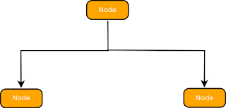
<Fig 1: Example of Hierarchical diagram - graph, layer, vertice/Node, edge>

To understand the Sugiyama layout algorithm, one has to first undertand what a visually appealing hierachial diagram is...then the code to automatically lay out the nodes because possible to write. The Sugiyama algorithm lays out a number of conditions that define what a visually appealing hierahial diagram should fulfil:

  1. The number of upward facing edges should be minimised (hierachy)
  2. Vertices should be placed in layers and as uniformly as possible in these layers (uniform distribution)
  3. The number of layers that the edges span should be minimised as much as possible (edges length minimization)
  4. Edges crossings should be minimized as much as possible (edge crossings minimization)
  5. Isomorphic graphs should be drawn identically (identical drawing)
  6. On each layer, vertices should be separated by the smallest distance possible (smallest separation)
  7. Neighbouring vertices in neighbouring layers should be placed as close as possible (closeness)
  8. Each vertice should be placed at the barycenter of the neighbouring vertices (balance)
  9. Bends should be minimised and edges made as straight as possible (linearity)
Don't worry if the above rules don't make sense right now. As you go through the blog post, it will become apparent what the terms 'barycenter' or 'isomorphic graph' mean.

Great, but what exactly is the Sugiyama algorithm and how does it work?

You will notice that above, i just mention what the Sugiyama algorithm is meant to do i.e. automatically lay out nodes in a hierarchial fashion...but it does not explicitly explain how that happens! Well, that';s what this section is all about...explaining how the Sugiyama algorithm works before i delve into the finer details using source code to provide a more detailed explanation.

The Sugiyama algorithm lays out the vertices in a graph (which coincidentally must be an acyclic digraph i.e. a directed graph (the edges have arrows or direction) and where no set of the edges form a cycle) in four stages
  1. The graph is made acyclic (i.e. any cycles formed by edges in the graph are removed). Details of how this is done below
  2. Vertices are assigned to layers in the graph
  3. The order of vertices in each layer is determined to reduce edge crossings as much as possible
  4. The position of the reordered vertices in each layer is determined to enhance balance and closeness.
Four mysterious stages(or algorithms)....that makes up Sugiyama!

There are obviously a lot more details that one will need to understand about each of the four steps above to clearly visualize the internals of Sugiyama. I will go through the four steps above using source code in java to clearly explain the four steps of Sugiyama and how they work.

Before we go on...

You are free to code the nodes/vertices and edges in your software as you see fit. I will explain the way i did it (a model i will be using all through the blog post) but feel free to adapt it to your source code once the stages below are clear.

The Graph that contains all the nodes and edges is denoted by the instance:

Graph graph = graphFrame.getGraph();

Edges are denoted and obtained from an arraylist of all the edges by the following code:

Edge e = (Edge)graphEdges.get(i); // i defines the index/counter for the current edge retrieved

Vertices are denoted and obtained by the following code:

Node n = (Node) graphNodes.get(t) // t is the counter for the current node retrieved

Step 1: making the graph Acyclic

I'll be a bad guy and let you figure this one out. Here's the reason why. When i was implementing the Sugiyama code, i knew the context that the software would be used...to lay out UML diagrams and if you think about it for a second, you will see that it becomes very difficult to create cycles..but i do promose to get back with code on how to do this later.

Step 2: Assigning vertices to layers


This step actually involves 2 steps; assigning vertices to layers in the graph and inserting dummy vertices. Dummy vertices...what's that? Well here's the thing. An edge in a graph(according to the Sugiyama algorithm should have a span of on 1) i.e. it should interconnect 2 vertices in adjacent layers. However, a vertice may be in layer 2 while connected to a vertice in layer 4; thus the edge would have a span of 2. Thus this step involves not just assigning the vertice to a layer but inserting dummy vertices     to edges that have a span of 1. So the question remains...what criteria is used to assign vertices/nodes to layers. Simple

First select the root nodes. These are the nodes that have edges flowing away from them but none coming into them. Then from each of the root nodes recursively go through all the nodes in the graph incrementing the level that a graph should have and assigning this level to the graph. If a node/vertice with a level assigned is encountered, check if the proposed level that it is to be assigned is less than the current level. If this is the case, assign it the proposed level (that is greater than the initial node level)


<fig 2: flow diagram of the algorithm to assigning levels to the nodes in a graph>

Here's a method referred to as getNodeChildren() with the signature indicated:

 private Node getNodeChildren(Node n, ArrayList graphEdges, Integer startCounter)
    {
        /**
         * The algorithmn for this function is as given below
         * starting with sourceNode 0,
         *      loop through all the edges
         *      find which edges have source Node as sourceNode0
         *      get the endNodes for these edges
         *      Add these endNodes as the childNodes for recursion
         *      increment the level that the nodes are found at
         */
        ArrayList endNodes = new ArrayList();
        if(n.getLayer()==-1||startCounter > n.getLayer())
        {
           n.setLayer(startCounter);
        }
        
        for(int i = 0 ; i 0)
        {
            startCounter += 1;
            for(int k = 0 ; k< endNodes.size(); k++)
            {                
                getNodeChildren((Node) endNodes.get(k),graphEdges, startCounter);
            }
        }
        
        // output the layer at which every node is found
       System.out.println("\nLayer: "
                    + n.getLayer()
                    + " Node: "
                    + n.toString());
        return n;
    }

Once all the nodes have a level(or layer number assigned to them, then comes the next step; adding dummy vertices where the edges have a span of more than 1. To do this, here is a simple function that gets the maximum span of all the edges:
 
     /**
     * Function gets the maximum span for all edges to allow
     * for the introduction of dummy vertices
     * @param edges
     * @return the max edge span
     */
    public int getMaxSpan(ArrayList edges)
    {
        int maxSpan = 0;

        for(int i=0;imaxSpan)?(endNodeLayer-startNodeLayer)
                    :maxSpan;
        }

        return maxSpan;
    }

Once the spans for all the edges have been determined, now comes the interesting part, the dummy vertices (and edges) are added:
 
     /**
     * function inserts dummy vertices and breaks down the
     * edges into segments in cases where the edges
     * span is >1
     * @param g the edge whose span is checked if>1
     */
    public void insertDummyVerticesAndEdges(Edge g)
    {
        /**
         * a. Loops through an edge
         *      i. finds out if the span is >1 by checking the
         *          start and End Node layers
         *      ii. Adds dummy vertices if span>1 at
         *          all calculated intermediate points
         *          (endNode.coords - startNode.coords)/span
         *      iii.Add segements to replace edge with start
         *          and end nodes indicated
         * e. remove the long edge whose span >1
         */
        Node startNode = g.getStart();
        Node endNode = g.getEnd();

        // get the span of the edge
        int span = endNode.getLayer()-startNode.getLayer();
        if(span>1)
        {
            System.out.println("\t* Edge "
                    + g.toString()
                    + " has span of "
                    + Integer.toString(span)
                    + " from "
                    + Integer.toString(startNode.getLayer())
                    + " to "
                    + Integer.toString(endNode.getLayer()));

            // calculate the incremental positions for the
            // display of the dummy vertices
            double xIncrement = (endNode.getBounds().getCenterX()
                                        - startNode.getBounds().getCenterX())/span;
            double yIncrement = (endNode.getBounds().getCenterY()
                                        - startNode.getBounds().getCenterY())/span ;
            
            // add dummy vertice at the various
            // layers that the edge spans
            // dummy_vertices_added  = (span -1)
            // @todo create a dummyNode vertice
            int noDummyVertices = span -1;
            Node previousNode = startNode;
            
            for(int i = 0 , currLayer = startNode.getLayer() + 1
                    ; i < noDummyVertices
                    ; i++ , currLayer++)
            {
                PointNode d = new PointNode();
                d.setLayer(currLayer);

                // show that it's a dummy variable
                d.setDummy(); 

                // add the Node to the graphs set of Nodes
                // get the dummy vertices coordinates
                final double xCoord = previousNode.getBounds().getCenterX()
                                    + xIncrement;
                final double yCoord = previousNode.getBounds().getCenterY()
                                    + yIncrement;

                // add Dummy Node
                graph.add(d, new Point2D.Double(xCoord,yCoord));

                System.out.println("\t\tAdded Dummy Node "
                        + d.toString()
                        + " at Layer "
                        + Integer.toString(d.getLayer())
                        + " and coords "
                        + d.getBounds()
                        + " ["
                        + Double.toString(xCoord)
                        + ","
                        + Double.toString(yCoord)
                        +"]");

                // add edge joining previous node
                // to newly created node
                // create new edge
                ClassRelationshipEdge r = new ClassRelationshipEdge();

                // connect the Nodes using the new edge
                graph.connect(r, previousNode, d);

                System.out.println("\t\t\tAdded new edge "
                        + r.toString()
                        + " at "
                        + previousNode.getBounds()
                        + " to "
                        + d.getBounds());                                
                                
                // make sure that the final edge between
                // the last dummy variable and endNode
                // is plotted
                if(i==noDummyVertices-1)
                {
                    // create new edge
                    ClassRelationshipEdge lastEdge = new ClassRelationshipEdge();

                    // connect the Nodes using the new edge
                    graph.connect(lastEdge, d, endNode);

                    System.out.println("\t\t\tAdded Last edge "
                        + r.toString()
                        + " at "
                        + d.getBounds()
                        + " to "
                        + endNode.getBounds());
                }

                // set the previous Node to the current
                // highlighted Node
                previousNode = d;
            }

            // since edge is decomposed to various
            // segments linking the various
            // dummy vertices, remove the edge
            graph.removeEdge(g);
        }
        else
        {
            // span is 1, OK
            // do nothing...
             return;
        }
    }

Step 3: Ordering the vertices to reduce the number of edge crossings:


So now all the nodes have been assigned to specific layers and dummy nodes (and by extension dummy edges) have been added. However, the vertices in each of the layers may be ordered in such a way that a lot of the edges connecting vertices(including the dummy vertices) between adjacent levels are crossing each other a lot. This is highly unacceptable and from the list of aethestic considerations below, the reduction of edge crossings is a key feature of the algorithm


<fig 3: a graph with a lot of edge crossings and one with few edge crossings>

So how do we reorder the vertices in each of the levels to ensure that the edge crossings are reduced as much as possible?

The number of edge crossings in vertices in adjacent layers is obtained by obtaining the adjacency matrices of the edges in adjacent layers, calculating the barycenters of these adjacency matrices and reordering the nodes so that the barycenters of the nodes are arranged from the smallest to the largest. Once a reordering occurs, the barycenters are recalculated and reordering done until the minimum number of edge crossings are obtained.


<fig 3: flow diagram illustrating the algorithm>


I realise that the description above is as cryptic as, well...trying to figure out how to make a chicken sing and so i'll try break down the various components of this step:

(a) Obtaining the adjacency matrices of adjacent layers in the graph where the vertices have been assigned layers


PS: I have had this article in my archives for very long before i decide to publish it. Please let me know if there are any errors &/ ommisions in the comment section below

Sunday, September 4, 2011

Enhancing Preservice training for Medical Students using ICDL - Optimistic or Deceiving?

August 26th marked a great day...and a bad one for me and at least 44 other folks. Could be more but at minimum 45. Let me explain. One of the programs that i work for has the mandate to improve pre-service training. To some of you folks, the term 'preservice' may be quite new if not outright confusing and so that i do not antagonize any further, i'll briefly describe it. 'Preservice' or more definitively 'Preservice Training' is pretty much the training you get while you are still in school(in whatever form that translates to for you...college, campus, nursery...); the training/learning you get before you get into 'service' or into your profession as a graduate. Our focus here was lecturers training students at Medical Teaching Centers; students in Clinical Medicine, Pharmacy, Environmental Science...that kind of thing. Clear? Great. Let's go on. This program that is working to fulfill this mandate decided to implement a very exciting idea, one that i must say i am very very proud of...to train lecturers on basic computer skills; and using the ICDL curriculum. Very exciting indeed!


Well, the program's lean and the team members few . So there weren't a lot of folks to volunteer on this one, just me. Don't get me wrong. I was excited to get 60 lecturers from colleges all across the country to comprehensively cover the basics on computer use but setting up the logistics was going to be a whole other thing, right. But then there was that tenet..."What does not kill you makes you stronger"...that encouraged me on. I rarely shudder at a task before taking it on, irregardless of how mundane, insurmountable or challenging it seems and I wasn't scared of this task either, i was just reflecting on the sheer volume of logistics to be addressed...and they didn't look pretty. What was to be done, you may wonder? Well quite a bit, really. I had to engage an accredited ICDL training college, find a 'spot' with a conducive environment and computer labs with 60 computers to spare and good internet access for 3 weeks, find accommodation for 60 folks, agree on a training schedule with the facilitators from the accredited ICDL college, arrange for transport from the hotel to the training venue and work with 60 or so colleges to get a participant from each...all in 2 weeks and with the companies hideous procedures and paper-work. I was starting to wonder if fate had an insidious plot to pit me against a seemingly Herculean task. Angst wouldn't even begin to describe my feelings at that point.


And at the end of all this the poignant question still hang in the air...would this really benefit the students at the various medical training colleges to obtain better instruction and learning?

Well, i was extremely optimistic advocating for this activity because (without sounding didactic :) ), i did believe that it really would translate to better teaching and learning. A number of lecturers lacked vital computing skills and as a recent survey conducted by a leading (if not the leading) human survey firm here in Kenya established, these lecturers are almost always exposed to a more technologically savvy and vibrant set of individuals in the form of their students. Students who are not only competent in the use of technology but relish its use and in my view would even prefer a mode of instruction that incorporated an advanced use of social networking (twitter and facebook...in case you are wondering), multimedia content in the form of DVD's and youtube videos, Interactive gaming and 3D simulation and eLearning platforms all offered using what is perhaps the world most ubiquitous consumer electronics platform(after the radio, of course); the mobile phone...among other platforms (tablets for instance, provide a very viable opportunity). Anyhow, back to the interesting stuff.

So to cut the long story short, i ended up with 49 faculty members from the various colleges nationwide, 44 of whom undertook the ICDL accreditation examinations! While the training was by large very well conducted, the testing was so poorly administered, it stuck out like a sore thumb to viciate the whole thing. The 'accredited' ICDL training college lacked the capacity to administer the exams (a fact that it was dishonest about) since it did not have the official testing software or its license key and rushed to get things done at the very last minute encumbering the lectures with a dueling one and half days of back-to-back exams and then flooding them with certificates of attendance to hide the shame and dissatisfaction of having none of the lecturers pass all the 7 otherwise straight forward exams. Indeed what was most distressing was that even these dismal results were only possible due to the assistance of an ICDL regional representative who dropped all pending activities and took time to urgently address this. So many other things could have gone wrong!

Anyhow, lessons learnt 1. Let the students undertake ICDL exams at a registered test center not at an alternative venue, it will prolong your life by a couple of days 2. Ensure that every little detail discussed with the ICDL accreddited college is verified...and when i say 'every little detail...' i mean exactly that 'every little detail...'. This may very well turn out to be your Achilles foot. It was mine. And never impose deadlines on the facilitators, let them take the wheel on this one. It is 'their training' in a way 3. Attend as many sessions of the training as possible. The participants feel secure and the facilitators accountable. It shouldn't be like this, I know. Oh well... 4. Make sure that the small but important details are addressed and fitted into the schedule. Aspects like administering the pretest and developing a schedule. They say an email(or anything on hard copy) is worth a thousand explanations. 5. Last but not least, evaluate and talk to both the participants and facilitators during the training. They will either be your best friends or enemies during the course of it.

I have no doubt that most if not all the participants obtained additional skills to navigate around a computer. I saw one participant who was exceptionally keen to learn but who previously had little exposure to computers and i was happy to see him learn something new every day. It is anticipated that this first set of lecturers will now be more confident and enthusiastic to use electronic learning materials, discuss the use of electronic learning materials and interact with their students using forums and emails. Inevitably this program will have to advocate for the inclusion of additional (in-service) content into pre-service curricula...and then the need to have precise and engaging learning content will become more apparent, urgent and necessary.